Production of Fischer Tropsch liquids
In cooperation with the biomass CHP in Guessing the first biomass-based
Fischer-Tropsch trial plant in Austria was realized in Guessing by Vienna
University of Technology (TUV) in the frame of the EC-project Renew and several national projects in 2005. A new
laboratory scale Fischer-Tropsch-Reactor (slurry reactor) in a side stream of
the existing allothermal fluidised bed gasifier at
BKG was designed and installed. The new FT-synthesis
plant operates in commercial environment and under permanent operation
conditions. By this the long term performance and
behaviour can be investigated. The catalysts used in the FT-slurry reactor are
pre-commercial FT-catalyst, but also research FT-catalysts are studied.
since 2004 now R&D is done on this
synthesis by Bioenergy2020+ together with his scientific partner Vienna
University of Technology. Here a gas treatment and a slurry FT reactor were developed, so that in combination with the steam
gasification, an economic production of FT raw product can be done.
The technical steps are
gasification, gas cleaning and treatment, the FT synthesis itself and the
Hydroprocessing of the raw FT products, as shown in Figure below

In the gasifier, the solid
feedstock is converted into synthesis gas, which
consist mainly of hydrogen and carbon monoxide. In the next step all impurities
like sulfur or chlorine components are removed and in
the gas conditioning, the correct pressure and H2:CO
ratio are adjusted. In the FT synthesis reactor, H2 and CO react on the
catalyst to a mixture of hydrocarbons, mainly paraffin's
with carbon numbers from C1 to C60. The raw product from the FT synthesis
consists mainly of waxes, but also here already a diesel fraction can be separated by vacuum distillation. The wax fraction is finally converted by hydroprocessing, which is a typical
refining process, into diesel and kerosene.
So 2
different types of fuels are produced in a FT synthesis:
- FT-fuels: are the product from the distillation of the FT raw
product and consists mainly of n-paraffins. FT-fuels have excellent properties as diesel additive, e.g. cetane number of 80, only the cold behaviour is not
optimal.
- HPFT-fuels:
are the product from the hydroprocessing of the FT waxes and their
chemical composition can be adjusted in the
hydroprocessing (mainly ratio between n- and iso-paraffins).
High share of iso-paraffins give an excellent
cold behaviour, so by hydroprocessing also kerosene can
be produced.
Both products from the FT
synthesis produce very high quality blending component for fossil diesel or
kerosene. For this reason not only the biomass conversion to FT products, but
also a cooperation with a refinery/fuel distributor is recomended
on the long term, where the refinery makes the final hydroprocessing, the
blending and also the distribution to the consumer.
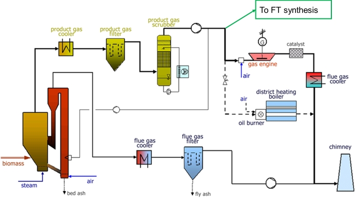
Description of the FT plant
At the location of Güssing a lab-scale plant for the conversion of
5Nm³/h of product gas is available. On this lab-scale plant first a
reliable gas treatment to remove catalyst poisons and afterwards the slurry FT
reactor itself was developed. This lab scale plant
uses the synthesis gas from the biomass CHP Güssing after removal of
particles and heavy tars, as shown in the figure below.
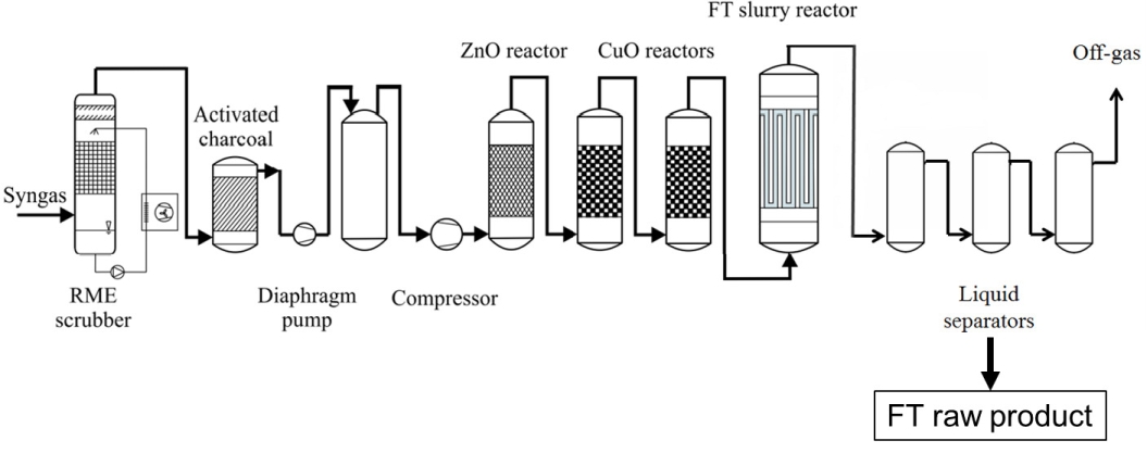
The flow chart below shows the test rig for the Fischer Tropsch synthesis. The FT synthesis consists of the following main parts:
- Gas drying by biodiesel scrubber
- 1st
gas cleaning by activated charcoal
- Compression
of the gas to 20-30 bar
- 2nd
gas cleaning by various adsorbers (ZnO, CuO, NaAlO 2 )
- slurry FT reactor
- separation
of FT raw product from tailgas
During the experiments different combinations of the gas cleaning
devices, different catalysts and operation parameters were tested.
The first step of drying is
necessary, because the product gas has a water content of about 10%, which
would condense in the gas compressions step. Here the gas is
cooled down to about 3°C in direct contact with biodiesel, to remove
the water content of the product gas. The second step of activated charcoal
removes the main amount of sulphur and other poisons (also to protect the gas
compressor). The compression of the gas consists of two steps, first a
diaphragm pump to about 5 bars and then a piston
compressor to 20-30 bars. The second gas cleaning consists of different adsorbers like ZnO or CuO to remove all catalyst poisons to below 10bbp.
After the gas treatment the clean gas is heated up to about 250°C and
fed into the FT-reactor. The Fischer Tropsch reaction takes place in a slurry
reactor (three phases; catalyst, gas, waxes) with a volume of 20 liters. The gas is leaving the reactor over sintered metal
filters. After the FT-reactor the Ft product together
with the tailgas is cooled down in several steps to
room temperature. Here the condenssation and
separation of the raw FT product takes place.
The liquid FT products are collected and distilled. The fraction up to 180°C is used as naphtha, from 180°C to 320°C is as diesel
and the fraction above 320°C are waxes. The
different liquid FT-products are delivered to the
partners in different projects.